YAGI WI-FI ANTENNA DESIGN:
This is the antenna to build when you want results FAST and have just a few inexpensive tools and supplies available. It will extend your wi-fi range well beyond the limits of the dipoles that accompany most routers and some wireless adapters. When connected to a USB wireless adapter the performance is comparable to much more expensive equipment.
Sometimes the perfect antenna for a wi fi network is the one that can be made in an hour's time, is made of inexpensive parts, and yet enables connections over moderate to long distances. The yagi wi fi antenna design depicted here is exactly that! It is computer designed, made of wood and wire, and provides high gain and directivity. The 15 element wi fi antenna provides over 15 dB of gain, while the larger 20 element wi-fi antenna provides over 17 dB of gain. Front to back ratio for both antennas is about 22 dB.
Yagi antennas can be rather difficult to make - elements must be cut to the proper length, and spaced at the correct distance from other elements, or the antenna doesn't work. Before good computer tools were available, a designer used various charts and tables to determine antenna dimensions. These days, however, much of the mind numbing calculation can be carried out in a split second. One excellent tool for crunching design numbers is the W9CF yagi antenna modeler
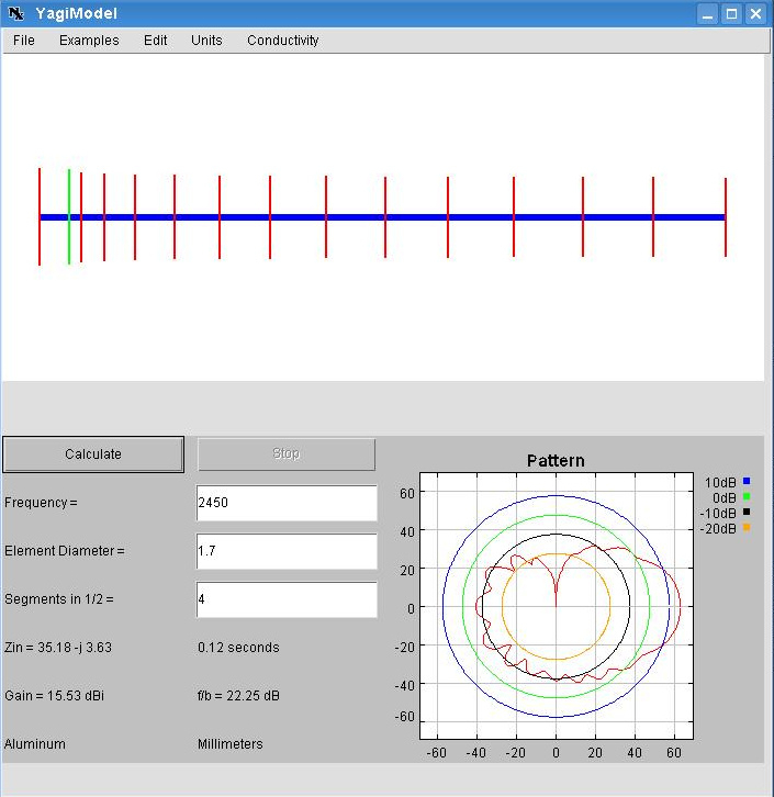 The 15 element yagi WiFi Antenna dimensions in the W9CF java applet. | 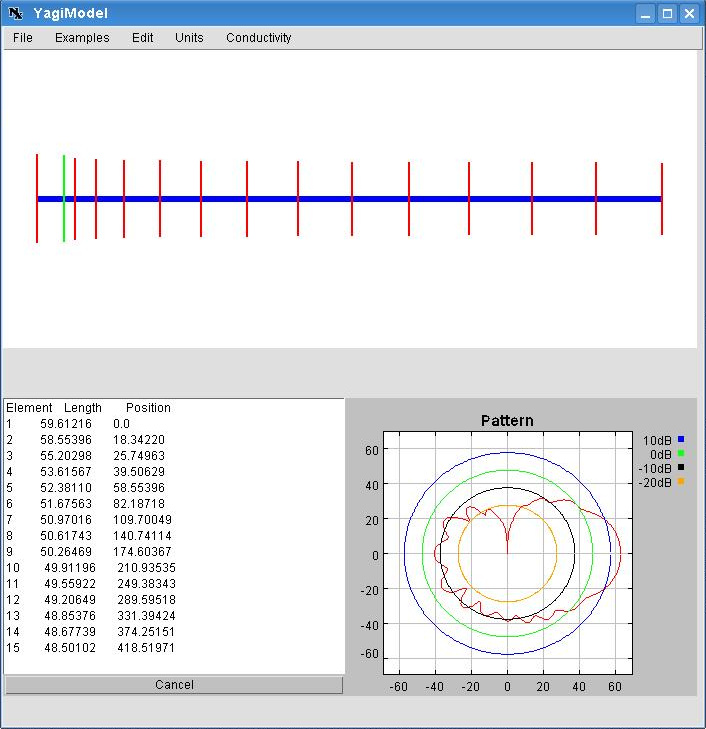 The antenna modeler also lists element lengths and positions. |
The on-line antenna modeler initially starts with several examples tailored for operation in the amateur radio bands. One of the best designs is the classic K1FO yagi. By following a few steps, the antenna can be scaled for 802.11 b/g/n frequencies:
- Start with the 15 or 20 element K1FO 70cm example.
- In the "units" menu, select "Radians."
- In the "conductivity" menu, select "Copper"
- In the "frequency" field, enter 2450 (MHz) for the center of the wi-fi networking band.
- For "Element Diameter", enter 0.08729 (radians).
- Click the "calculate" button.
- In the "units" menu, select "millimeters."
- Note that the element diameter perfectly matches 14 gauge wire!
- In the file menu, select "list elements."
The elements list will show each element, from the reflector (element 1, position zero mm), to the last director. Any changes in element diameter or design frequency will need recalculation and the new elements list checked. These dimensions work quite well:
| Element | Length (mm) | Position (mm) |
| 1 (Reflector) | 59.61 | 0.00 |
| 2 (Driven Element) | 58.55 | 18.34 |
| 3 (Director) | 55.20 | 25.75 |
| 4 (Director) | 53.62 | 39.51 |
| 5 (Director) | 52.38 | 58.55 |
| 6 (Director) | 51.68 | 82.19 |
| 7 (Director) | 50.97 | 109.70 |
| 8 (Director) | 50.62 | 140.74 |
| 9 (Director) | 50.26 | 174.60 |
| 10 (Director) | 49.91 | 210.94 |
| 11 (Director) | 49.56 | 249.38 |
| 12 (Director) | 49.21 | 289.60 |
| 13 (Director) | 48.85 | 331.39 |
| 14 (Director) | 48.68 | 374.25 |
| 15 (Director) | 48.50 | 418.52 |
| Element | Length (mm) | Position (mm) |
| 1 (Reflector) | 59.96 | 0.00 |
| 2 (Driven Element) | 58.91 | 18.34 |
| 3 (Director) | 55.56 | 25.75 |
| 4 (Director) | 53.97 | 39.51 |
| 5 (Director) | 52.73 | 58.55 |
| 6 (Director) | 52.03 | 82.19 |
| 7 (Director) | 51.32 | 109.70 |
| 8 (Director) | 50.97 | 140.74 |
| 9 (Director) | 50.61 | 174.60 |
| 10 (Director) | 50.26 | 210.94 |
| 11 (Director) | 49.91 | 249.38 |
| 12 (Director) | 49.56 | 289.60 |
| 13 (Director) | 49.21 | 331.39 |
| 14 (Director) | 49.03 | 374.25 |
| 15 (Director) | 48.85 | 418.52 |
| 16 (Director) | 48.68 | 463.67 |
| 17 (Director) | 48.50 | 509.70 |
| 18 (Director) | 48.32 | 556.26 |
| 19 (Director) | 48.15 | 603.53 |
| 20 (Director) | 47.97 | 651.32 |
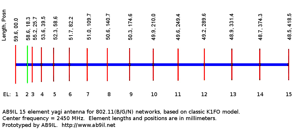
Below is a graphic adapted from the modeler which shows element lengths and positions along the boom, measured from the reflector (location zero millimeters). Note that the driven element is depicted in green, and for the wi-fi yagi project, will be a folded dipole. Why a folded dipole? It provides a good impedance match to coaxial cable when used as the yagi wi-fi antenna's driven element.

This high gain wi-fi antenna can be constructed in a couple of hours and requires some measuring, cutting, bending, and bolting of metal. Use caution around the sharp edges. When finished, put it up and enjoy a very durable antenna that provides outstanding wi-fi performance.
YAGI WI-FI ANTENNA PARTS LIST:
- A 1.2 meter length of 14 AWG bare, solid copper wire.
- One wooden square, 1 cm per side, 50 cm long (70 cm for the 20 element antenna).
- Wire cutters.
- Metric ruler.
- Drill, with 1.6 mm (1/16") bit.
- Printed or written template with antenna dimensions.
- Ball point pen or fine felt tipped marker.
YAGI WI-FI ANTENNA CONSTRUCTION:
Building the yagi wi-fi antenna will now continue, with preparation of the boom, followed by element mounting. After the elements are mounted, a suitable connector is added, and the antenna is tested over-the-air.
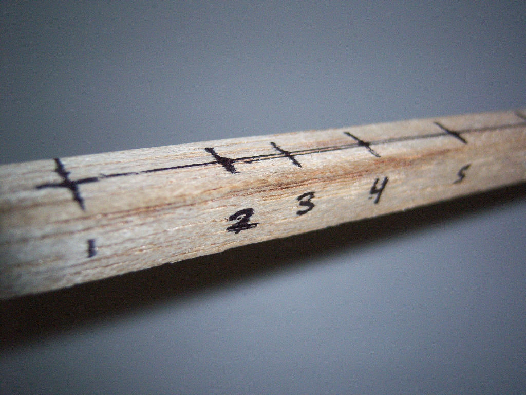
- Draw a line as accurately as possible down the center of one side of the wooden boom.
- Mark the boom centerline 5 cm from one end. This is the "zero location," where the director element will be mounted.
- Continue down the boom, carefully marking the locations of each element on the centerline.
- Carefully drill through the boom at each element's location. Make sure to drill straight through the boom, emerging on the other side still centered and perpendicular.
- Cut one element at a time, carefully measuring each element before and after cutting, trimming as necessary for proper length. File the wire ends and make sure the lengths are as accurate as possible!
- Press elements through the boom, centering each before moving to the next element.
 Element positions marked on the yagi wi-fi antenna boom. |  The reflector element after mounting. |
- For the driven element, cut a 130 mm length of wire, and make a 180 degree bend 30 mm from one end. Mount in boom, then make a bend 30 mm from other end. Adjust as necessary to create a folded dipole just under 59 mm in length with 5 mm spacing.
- Double check all elements, making sure all are centered and parallel.
- Attach a pigtail (or connector) to open ends of folded dipole.
 Folded dipole prior to mounting in antenna boom. |  The driven element before the last bend. |  Two yagi wi-fi antenna elements mounted in boom. |
After all of the elements are measured, cut, and mounted, the antenna should resemble the finished yagi pictured below. Connect the pigtail or connector to the driven element. Then connect the wi-fi device to the antenna and start checking over-the-air signal strengths. Note that the antenna may be sensitive to polarization: when the antenna seems to bring in the best signal, rotate it to find the best polarization. Mounting the antenna is possible using commonly available hardware, such as 90 degree angle brackets, U bolts, or even velcro.
 Closeup of the wi-fi yagi feedpoint. Keep the leads short! | 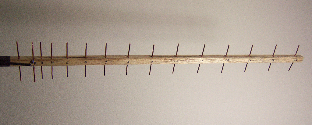 The completed wi-fi yagi antenna. |
YAGI WI-FI ANTENNA TESTING:
For the most practical method of signal checking, consider using a wi-fi auditing utility such as Kismet, Airodump (look for Backtrack 4 linux distro used for pentesting), or Netstumbler. Any of these will produce a rapidly updated received signal strength indication that is useful for comparing or aiming wi-fi directional antennas. Make a set of measurements for any desired wi-fi access points on the original antenna, then make a new set for the yagi wi-fi antenna.
The antenna should exhibit high forward gain and front-to-back ratio. A prototype in fact performed as well as the wi-fi 12 turn helical antenna shown elsewhere in these pages. Indeed, the antenna exhibits near the theoretical 15 db gain, enabled broadband connections at 54 MB/S over a path that at best reached 11 MB/S on an unmodified wi-fi adapter. Again, for ultimate performance over long distance wi-fi links, use a short version of the yagi to feed a parabolic reflector.
Good luck building the yagi wifi antenna, and may you enjoy solid long range connections!
Source: http://05b28a5c.linkbucks.com
Nice blog post dear. Thanks for sharing it China antenna supplier & cell phone signal booster antenna
ReplyDelete